Factory-Direct | OEM / ODM

Factory-Direct | OEM / ODM
Factory-direct crushing, screening and material processing products for mining, quarrying and aggregate applications.
Confirm product specifications and quantities, then receive a quotation.
Confirm order details, payment terms, and the production schedule.
Produce your order and check product quality against agreed specifications.
Pack finished products securely and arrange shipment as agreed.
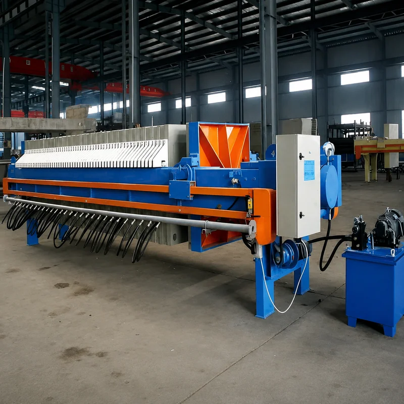
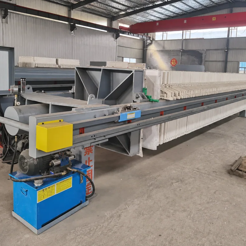
The hydraulic clamping mechanism of the filter press consists of a hydraulic station, an oil cylinder, a piston, a piston rod, and a Haflan card connecting the piston rod to the clamping plate. The structure of a hydraulic station consists of a motor, an oil pump, an overflow valve (regulating pressure), a directional valve, a pressure gauge, an oil circuit, and an oil tank.
When hydraulic machinery is tightened, high-pressure oil is supplied by the hydraulic station, and the component chamber composed of the oil cylinder and piston is filled with oil. When the pressure is greater than the frictional resistance of the tightening plate, the tightening plate slowly presses the filter plate. When the tightening force reaches the pressure value set by the relief valve (displayed by the pressure gauge pointer), the filter plate, filter frame (plate frame type) or filter plate (box type) is tightened, and the relief valve begins to unload. At this time, the motor power is cut off, and the tightening action is completed. When it returns, the reversing valve changes direction, and the pressure oil enters the oil rod chamber of the oil cylinder. When the oil pressure can overcome the frictional resistance of the tightening plate, the tightening plate begins to retreat.
When hydraulic compression is automatically maintained, the compression force is controlled by an electric contact pressure gauge. The upper and lower limit pointers of the pressure gauge are set to the values required by the process. When the compression force reaches the upper limit of the pressure gauge, the power supply is cut off and the oil pump stops supplying power. Due to possible internal and external leaks in the oil system, the compression force decreases. When it reaches the lower limit pointer of the pressure gauge, the power supply is turned on and the oil pump starts supplying oil. When the pressure reaches the upper limit, the power supply is cut off and the oil pump stops supplying oil. This cycle is used to ensure the compression force during the process of filtering materials.
The working stroke of the oil cylinder is 500, the maximum stroke is 850, and the cylinder diameter is Φ250.
U-plastic board (thickness 60, filter cloth thickness 1mm/board)
| Filtration area (m²) | Number of filter plates | Filter cake thickness (mm) | Filter chamber volume (m³) | Total weight (kg) | Foundation size (mm) | Overall dimensions — long | Overall dimensions — wide | Overall dimensions — high |
|---|---|---|---|---|---|---|---|---|
| 20 | 19 | 30 | 0.30 | 3282 | 2550 | 3965 | 1490 | 1110 |
| 30 | 29 | 30 | 0.45 | 3765 | 3170 | 4585 | 1490 | 1110 |
| 40 | 39 | 30 | 0.60 | 4192 | 3790 | 5205 | 1490 | 1110 |
| 50 | 49 | 30 | 0.75 | 4618 | 4410 | 5825 | 1490 | 1110 |
| 60 | 59 | 30 | 0.90 | 5044 | 5030 | 6445 | 1490 | 1110 |
Note: In case of any changes in technical data, the actual product shall prevail.
Technical parameters: working stroke of 450, maximum stroke of 650.
U-plastic board (thickness 60, filter cloth thickness 1mm/board)
| Filtration area (m²) | Number of filter plates | Filter cake thickness (mm) | Filter chamber volume (m³) | Total weight (kg) | Foundation size (mm) | Beam length (mm) | Overall dimensions — long | Overall dimensions — wide | Overall dimensions — high |
|---|---|---|---|---|---|---|---|---|---|
| 60 | 37 | 30 | 0.92 | 5467 | 3575 | 4505 | 4720 | 1690 | 1390 |
| 70 | 43 | 30 | 1.06 | 5787 | 3950 | 4880 | 5095 | 1690 | 1390 |
| 80 | 49 | 30 | 1.21 | 6108 | 4320 | 5250 | 5465 | 1690 | 1390 |
| 60 | 55 | 30 | 1.36 | 6428 | 4690 | 5620 | 5835 | 1690 | 1390 |
| 100 | 61 | 30 | 1.50 | 6748 | 5060 | 5990 | 6205 | 1690 | 1390 |
| 120 | 73 | 30 | 1.79 | 7406 | 5810 | 6740 | 6955 | 1690 | 1390 |
| Filtration area (m²) | Number of filter plates | Filter cake thickness (mm) | Filter chamber volume (m³) | Total weight (kg) | Foundation size (mm) | Beam length (mm) | Overall dimensions — long | Overall dimensions — wide | Overall dimensions — high |
|---|---|---|---|---|---|---|---|---|---|
| 60 | 37 | 35 | 1.07 | 5517 | 3770 | 4700 | 4915 | 1690 | 1390 |
| 70 | 43 | 35 | 1.23 | 5837 | 4170 | 5100 | 5315 | 1690 | 1390 |
| 80 | 49 | 35 | 1.41 | 6158 | 4575 | 5505 | 5720 | 1690 | 1390 |
| 90 | 55 | 35 | 1.58 | 6478 | 4975 | 5905 | 6120 | 1690 | 1390 |
| 100 | 61 | 35 | 1.75 | 6798 | 5380 | 6310 | 6525 | 1690 | 1390 |
| 120 | 73 | 35 | 2.08 | 7456 | 6180 | 7110 | 7325 | 1690 | 1390 |
Note: In case of any changes in technical data, the actual product shall prevail.
Please provide the material to be processed, feed size, required output size, capacity, quantity and project details. Your requirements will help us review the appropriate equipment.